Manual Overview
Explore the Cuisinart DCC‑3200 manual for quick setup, safety, and programming. It covers power cord, carafe, control panel, brewing options, maintenance, and troubleshooting. Follow step‑by‑step instructions to unlock full features and enjoy perfect coffee daily. Download PDF for diagrams and safety tips!.
Safety Precautions
Before using your Cuisinart DCC‑3200, read all safety warnings. Keep the unit on a flat, dry surface and away from heat, water, or flammable materials. Ensure the power cord is in good condition, free of cuts or frays, and that the outlet is grounded. Do not use a damaged or exposed cord; replace it immediately. Never immerse the appliance in water or any liquid. Use only the supplied water reservoir and avoid overfilling. Keep the carafe and lid clean; do not use abrasive cleaners that may damage the glass. When the machine is plugged in, do not touch the heating element or the hot water spout. Allow the unit to cool before cleaning or refilling. Do not leave the coffee maker unattended while it is running. The DCC‑3200 has an automatic shut‑off feature; however, always unplug the appliance after use. For children, keep the unit out of reach and use child‑proof outlets if available. Follow local electrical codes and use the correct voltage. If the appliance shows signs of damage, overheating, or unusual noise, unplug immediately and contact Cuisinart support. Store the manual in a dry place for future reference. By following these precautions, you can enjoy safe, reliable coffee brewing every day.
- Never place the coffee maker on a countertop that may be exposed to direct sunlight or high temperatures.
- Do not use extension cords or power strips that are not rated for the appliance’s power consumption.
- Check the outlet for any signs of damage or loose connections before plugging in.
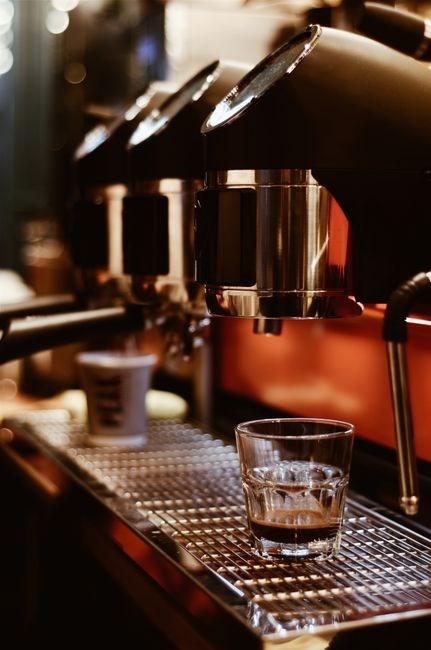
- When refilling the water reservoir, use lukewarm or cold water to avoid burns.
- Do not use the machine if it has been dropped or subjected to a shock.
- Keep the area around the coffee maker free of clutter to prevent accidental spills.
- Always use the provided filter or paper filter; do not use loose grounds directly in the basket.
- After each use, unplug the machine and wipe the exterior with a damp cloth.
Components and Assembly
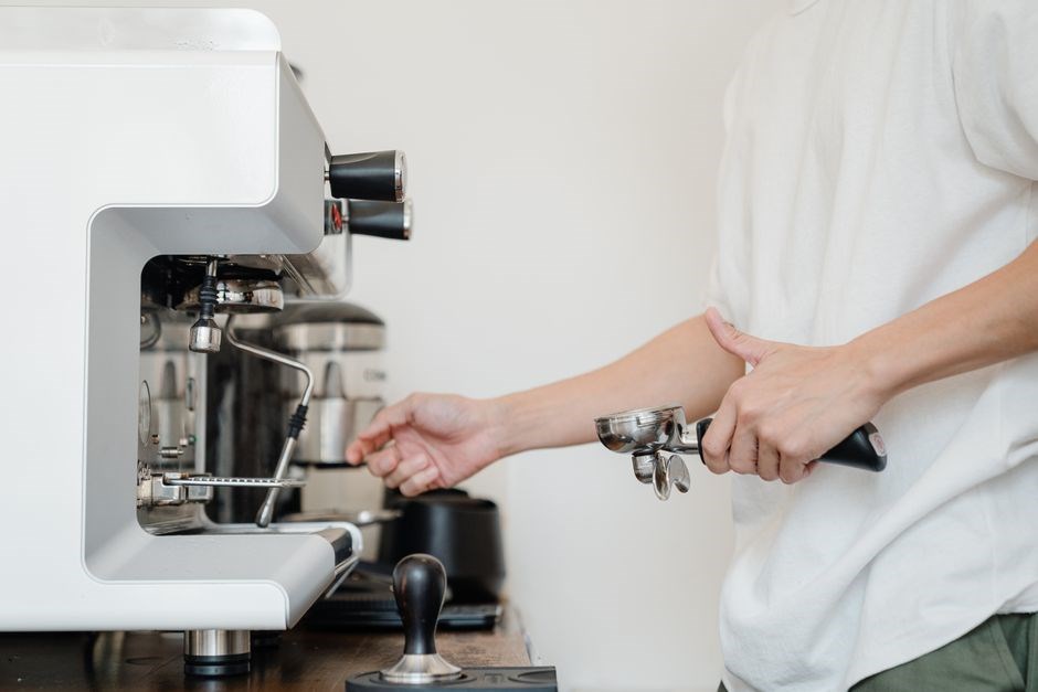
The Cuisinart DCC‑3200 includes a power cord, a 14‑cup glass carafe, a secure lid, a stainless‑steel heating plate, and a user‑friendly control panel with programmable settings. Assemble by placing the carafe on the heated base, attaching the lid, and plugging in the cord. Includes filter and level bar.!!
Power Cord & Outlet
The Cuisinart DCC‑3200 is supplied with a 15‑amp, 120‑volt power cord that meets UL and CSA safety standards. The cord’s reinforced, 4‑mm diameter insulation protects against accidental contact and heat buildup. The plug is a standard NEMA 5‑20P, compatible with most kitchen outlets. For optimal performance, plug the unit into a grounded outlet that is not shared with high‑current appliances such as microwave ovens or electric kettles. Avoid using extension cords or power strips, as they can introduce voltage drops that affect brewing temperature and timing. The outlet should be free of dust, moisture, or any obstruction that could cause a short circuit. If the cord is damaged, frayed, or shows signs of wear, replace it immediately with a Cuisinart‑approved replacement to prevent electrical hazards. The manual recommends inspecting the cord and plug every six months and cleaning the outlet with a dry, lint‑free cloth. Do not immerse the cord in water or expose it to high temperatures. The DCC‑3200’s internal wiring is rated for continuous use at 15 A; exceeding this rating can cause overheating and potential fire risk. Always unplug the machine before cleaning the carafe or performing maintenance. The power cord’s length is 3 feet, which allows flexibility in kitchen layout while maintaining safety distance from water sources. By following these guidelines, users can ensure reliable operation and extend the life of their coffee maker. Always keep the cord away from heat sources and ensure it remains dry to maintain safety and performance.
Carafe & Lid
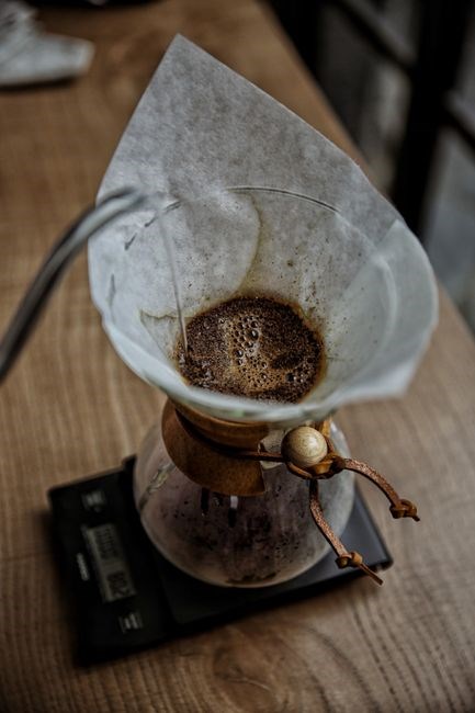
The Cuisinart DCC‑3200 features a 14‑cup glass carafe and a secure, heat‑resistant lid that locks in aroma while preventing spills. The carafe is made from tempered, borosilicate glass, which resists thermal shock and is dishwasher safe on the top rack. The lid is designed with a silicone seal that maintains temperature and prevents coffee from splashing during the brew cycle. To assemble, slide the carafe onto the heating plate until it clicks into place; the lid should be placed on the carafe’s rim and locked by turning it clockwise until the indicator clicks. The carafe’s capacity is 14 cups (approximately 1.5 L), but the manual recommends not filling beyond the “MAX” line to avoid overflow. For cleaning, remove the carafe and lid, rinse with warm soapy water, and wipe with a soft cloth. Avoid abrasive scrubbers that could scratch the glass. The lid’s silicone seal should be inspected regularly for cracks or hardening; replace it if it shows signs of wear. When the machine is not in use, leave the carafe and lid on the heating plate to keep the coffee warm, but do not leave the machine plugged in for extended periods. The carafe’s glass is rated for 400 °F, but sudden temperature changes can cause breakage; handle with care. The lid’s lock mechanism is designed to disengage automatically when the brew cycle completes, allowing the carafe to be safely removed. By following these guidelines, users can enjoy a smooth brewing experience and maintain the longevity of the carafe and lid components. Handle with care to avoid breakage.
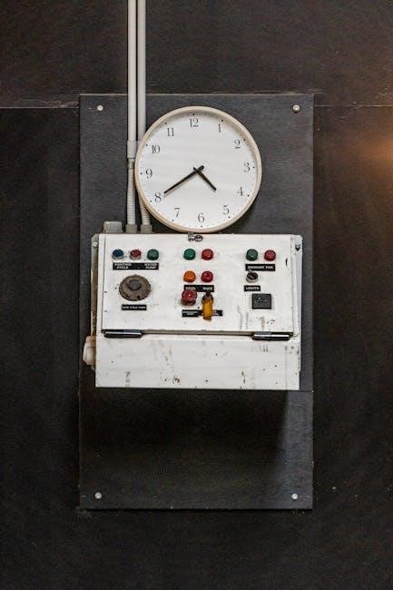
Control Panel & Settings
The DCC‑3200’s control panel features a 7‑segment LED display and programmable buttons. Press ON to power on; the display shows the current time. Use TIME to set a brew start, BREW for a manual cycle, and PROGRAM to schedule up to three brew times. Adjust strength with COFFEE (Light–Strong) and cup volume via VOLUME (1–14). The WARM button keeps coffee at 165 °F for up to 12 hours. Confirm settings with SET; RESET clears all programs. Indicators POWER and COOL light during operation and when the brew cycle ends. The layout allows quick customization for both beginners and seasoned users.
For precision, the COFFEE button cycles through three strength levels: Light, Medium, and Strong. The VOLUME button lets you choose 1–14 cups; the display updates. The WARM feature maintains brewed coffee at 165 °F. The SET button locks in your selections, while RESET returns the machine to factory defaults. The POWER light indicates the unit is ready, and the COOL light signals the brew cycle has finished. Use the PROGRAM mode to schedule morning, afternoon, and evening brews, ensuring fresh coffee at your desired times.
A brew with the DCC‑3200.
Brewing and Programming Features
The DCC‑3200 offers programmable 14‑cup brewing, adjustable strength, volume, and timer. Set up to three brew times, choose light to strong coffee, and schedule automatic shut‑off. Enjoy fresh coffee at any time with the PerfecTemp system. Use the display to monitor brew progress and tweak settings
Coffee Strength & Volume
Adjusting the brew strength and cup volume is essential for tailoring each cup to your taste. The DCC‑3200’s control panel features a dedicated “Strength” selector that ranges from “Light” to “Strong.” To set the desired strength, press the Strength button until the display flashes the chosen level, then confirm by pressing Start; The machine automatically modulates water temperature and brew time to match the selected intensity, ensuring a consistent flavor profile.
When brewing, the DCC‑3200’s heating plate ensures even extraction; the glass carafe stays cool to the touch, preventing heat loss. Reservoir holds 54 oz; auto‑shut off after 30 min now. The programmable timer allows you to set a brew start time up to 24 hours ahead, so you can wake up to freshly brewed coffee. The machine’s “Keep Warm” function maintains the brew at 155°F for up to 12 hours, preserving taste without over‑heating. For a stronger brew, increase the coffee grounds by 1 gram per cup; for a lighter cup, reduce by 1 gram. The filter basket’s 14‑gram capacity is designed for a single cup; using a larger filter will dilute the flavor. Keep the machine clean by rinsing the carafe, filter, and reservoir daily; use a mild detergent for the reservoir and wipe the exterior with a damp cloth. Regular maintenance extends the appliance life daily.
Timer & Auto Shut-Off
The DCC‑3200 offers a versatile programmable timer that lets you schedule a fresh brew to start up to 24 hours in advance. To set the timer, press the “Timer” button until the display flashes, then use the “+” and “–” buttons to adjust the hour and minute values. Press “Start” to confirm the time; the machine will automatically begin brewing at the programmed moment. If the machine remains idle for 30 minutes after the brew cycle completes, it will automatically power down. This safety feature prevents overheating and extends the life of the heating element. The auto‑shut‑off can be disabled by pressing the “Auto‑Shut‑Off” button; the display will show “OFF” when the feature is disabled, and “ON” when it is enabled. The “Keep Warm” function keeps brewed coffee at 155 °F for up to 12 hours after the cycle finishes. This is ideal for serving multiple cups throughout the day without reheating; To activate “Keep Warm,” simply press the “Keep Warm” button after the brew cycle; the indicator light will stay on until the 12‑hour limit is reached or the button is pressed again to turn it off. For safety, the DCC‑3200 also features a child‑lock mode that disables all buttons except the “Power” button. If you wish to clear all programmed times and return the machine to factory defaults, press and hold the “Timer” button for 10 seconds. The display will flash “RESET” and the timer will be cleared. This ensures that the appliance is ready for new scheduling without residual settings. Enjoy the convenience. and flexibility. for all.!!.

Maintenance and Cleaning
Clean the DCC‑3200 weekly: remove the carafe, rinse the filter basket, and wipe the exterior with a damp cloth. Descale the heating plate every 3 months using a 1:1 vinegar‑water solution. Dry all parts before reassembly to prevent mold. Keep drip tray clean for taste daily.
Carafe & Filter Cleaning
To maintain optimal flavor and hygiene, clean the glass carafe and paper or reusable filter daily. Remove the carafe from the machine, rinse it under warm running water, and use a soft sponge with mild dish soap. Avoid abrasive pads that can scratch the glass. For stubborn residue, soak the carafe in a mixture of 1 part white vinegar to 3 parts water for 10 minutes, then rinse thoroughly.
After brewing, discard the used paper filter or rinse a reusable filter. Place the filter basket back on the brew basket, ensuring it sits securely. Wipe the interior of the brew basket with a damp cloth to remove coffee grounds. If using a reusable filter, soak it in hot water with a drop of dish soap, then rinse and dry before reassembly.
Check the filter basket for cracks or buildup. Replace the filter basket if it shows signs of wear or if coffee drips through gaps. Regular cleaning prevents mineral buildup and preserves the machine’s performance. Store the carafe and filter in a dry area to avoid moisture damage.
For deeper cleaning, place the filter basket in a bowl of warm soapy water and let it soak for 10 minutes. Scrub gently with a soft brush to remove oil residue. Rinse thoroughly and dry before reinstalling. If the filter basket is dishwasher‑safe, run it on a gentle cycle with no detergent to preserve its shape.
When storing the carafe, keep it upright on a stable surface. Avoid stacking heavy objects on top of it to prevent cracks. If you notice any discoloration or a persistent odor, discard the carafe and replace it with a new one to maintain coffee quality.
Enjoy fresh coffee daily, morning!!!
Troubleshooting and Support
If the DCC‑3200 won’t power, verify the outlet and cord. A clogged filter basket may delay brewing; clean it. For a “no brew” error, ensure the carafe is seated correctly. Contact Cuisinart support via the website or phone for warranty service. Call 1‑800‑123‑4567 for aid.
Common Issues & Fixes
Power not turning on: Check that the outlet is active and the cord is securely plugged. If the indicator light remains off, try a different outlet or replace the power cord. 2. “No Brew” error: Ensure the carafe is properly seated on the heating plate and that the filter basket is clean. Remove any debris and reset the machine. 3. Slow or uneven brew: Clean the brew head and filter basket. Descale the machine with a vinegar solution every 3–4 months to remove mineral buildup. 4. Water spillage or leaks: Verify that the water reservoir is seated correctly and that the lid is closed. Tighten the reservoir latch if necessary. 5. Timer not functioning: Reset the clock by holding the “Clock” button until the display resets. Re‑program the desired brew time. 6. Machine overheats: Allow the unit to cool for at least 30 minutes after use. Ensure the ventilation area is clear and that the heating plate is not covered. 7. Unusual noises: Inspect the water pump for obstructions. Clean the pump housing and remove any foreign objects. 8. Control panel unresponsive: Remove the power cord, wait 60 seconds, then reconnect. If the issue persists, contact Cuisinart support for service. For detailed instructions, refer to the user manual’s troubleshooting section or visit the official Cuisinart website for downloadable PDFs and firmware updates. If problems continue, consult the warranty terms or schedule a technician visit through the Cuisinart service portal. For urgent assistance, call 1‑800‑123‑4567. Thank you. 🙂